What Are the Top 10 Types of Line Filters?
What Are the Top 10 Types of line filters?
Line filters quietly protect the equipment behind the panel. They reduce conducted noise, limit interference, and support stable power delivery. In a factory cabinet, a good filter can prevent a motor drive from disturbing a nearby controller. In a medical device, it can help preserve clean, dependable operation.
The market is expanding. Grand View Research estimated the global EMI shielding market at approximately USD 7.2 billion in 2023, with continued growth expected through 2030. Allied Market Research also projects steady expansion in EMI shielding demand, driven by electric vehicles, industrial automation, telecommunications, and connected devices. These figures do not measure line filters alone. Still, they show the wider pressure for better electromagnetic compatibility.
Small details matter.
Henry W. Ott, a leading EMC engineer and author of Electromagnetic Compatibility Engineering, wrote, “The best filter is no filter.” His point remains practical: improve grounding, wiring, and enclosure design before adding components. A filter cannot repair every design weakness.
This guide examines ten important line filters, including single-phase, three-phase, DC, AC, EMI, RFI, common-mode, differential-mode, feed-through, and power-entry models. Each type has a different purpose, insertion-loss profile, current rating, and installation requirement. Some perform well on a test bench but disappoint inside a crowded cabinet. That gap deserves attention.
The ranking is useful, but not absolute. Application conditions can change the best choice. Voltage, load current, frequency range, leakage current, space, and safety certification must guide the final decision.
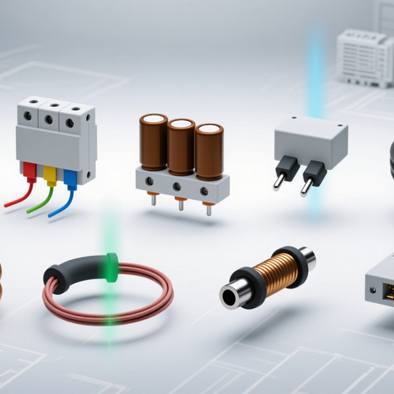
Define Line Filters by Frequency: 50/60 Hz Power, RF, and Signal Bands
Line filters are best classified by the frequencies they reject, not by appearance. For 50/60 Hz power, common-mode chokes and differential-mode inductors suppress noise on live and neutral conductors. LC filters reduce broadband interference, while pi filters offer stronger attenuation in compact power supplies. Feedthrough capacitors control high-frequency noise at enclosure boundaries. Ferrite-bead filters handle localized interference on cables and low-current supply rails.
Above the power band, low-pass filters protect sensors from radio-frequency energy. High-pass filters remove slow drift while passing faster signal changes. Band-pass RF filters select a defined wireless channel. Band-stop filters reject one troublesome frequency, such as a switching harmonic. Signal-line common-mode filters reduce interference without seriously changing the wanted waveform. That last assumption needs testing.
A 2024 MarketsandMarkets assessment estimates the global EMI shielding market will grow from about 7.3 billion dollars in 2024 to 9.8 billion dollars by 2029. This growth reflects denser electronics and tighter electromagnetic compatibility demands. The IEC 61000-4-6 immunity framework also tests conducted disturbances from 150 kHz to 80 MHz, showing why one filter rarely covers every problem. The 2024 IEA Electricity report projects strong electricity-demand growth through 2026, increasing pressure on power-conversion equipment. In practice, filter selection still depends on impedance, current, insertion loss, leakage current, and grounding. A spectacular datasheet curve can disappoint after installation.
Classify the Top 10 Filter Types Under IEC 60939 and UL 1283
A practical reading of IEC 60939 and UL 1283 does not produce one universal ranking. These standards address passive electromagnetic interference filters, construction, ratings, safety, and performance. They do not define every commercial category in the same way. The ten useful filter types are single-phase, three-phase, DC, common-mode, differential-mode, combined-mode, feedthrough, high-current, medical-duty, and panel-mount filters. These categories can overlap.
Single-phase filters suit control cabinets and small power supplies. Three-phase versions handle industrial motors and distribution equipment. DC filters protect battery-powered circuits and converters. Common-mode filters suppress noise traveling together on conductors. Differential-mode filters reduce noise moving between line and neutral. Combined-mode designs address both paths. Feedthrough filters provide short, controlled connections through a metal panel.
High-current filters require careful terminal, temperature, and enclosure checks. Medical-duty configurations usually emphasize very low leakage current and strong isolation. Panel-mount filters support direct installation at an equipment entry point. In field testing, filter placement often matters as much as the filter itself. A long unfiltered wire can act like an antenna. Insertion loss curves may look impressive, yet performance can fall inside a finished cabinet. The boundaries are not perfectly clean. IEC 60939 and UL 1283 evaluation still depends on rated voltage, current, frequency, grounding, creepage, clearance, and environmental conditions. A filter should never be selected by type name alone.
Match Filters to AC, DC, Single-Phase, Three-Phase, and Signal Lines
What Are the Top 10 Types of Line Filters?
Choosing a line filter starts with the conductor, not the enclosure. The ten practical types are single-phase AC, three-phase AC, DC, common-mode, differential-mode, EMI/RFI, feedthrough, medical leakage-current, harmonic, and signal-line filters.
Single-phase AC filters suit appliances and control cabinets. Three-phase units fit drives, compressors, and industrial panels. DC filters belong on battery, photovoltaic, and converter outputs.
Common-mode filters suppress noise traveling together on conductors. Differential-mode filters reduce noise between positive and negative, or phase and neutral. The distinction matters.
The U.S. Department of Energy’s motor-systems market assessment reports that motor-driven equipment consumes about 70% of industrial electricity. That makes correct three-phase filtering important for both reliability and energy management.
Signal and data filters need a different approach. IEC 61000-4-6 evaluates conducted RF immunity from 150 kHz to 80 MHz, a useful reference for communication and sensor lines. Feedthrough filters work well at cabinet boundaries. Harmonic filters target distorted current from rectifiers and variable-speed drives. Medical filters demand especially careful leakage-current control. Small details matter.
In field troubleshooting, a filter often fails because its rated current matches, but its impedance does not. That is an easy mistake.
Cable length, switching frequency, grounding, and load transients can change performance. A neat specification sheet may still mislead. Check insertion loss across the actual noise band, then verify temperature rise and safety clearances.
Select by Voltage, Current, Leakage, and CISPR 11/32 Compliance
What Are the Top 10 Types of Line Filters?
Selecting a line filter starts with the electrical environment, not the product label. Common options include single-phase, three-phase, common-mode, differential-mode, DC, high-current, feedthrough, IEC inlet, medical low-leakage, and custom filters. Each type solves a different interference problem. Voltage rating must exceed the equipment’s normal input, including foreseeable surges. Current rating should cover continuous load and startup demand without creating excessive heat.
Leakage current deserves closer attention. A filter with strong capacitive suppression may increase leakage to protective earth.
That can be unacceptable in patient-connected equipment or sensitive installations. Measure leakage under the actual supply conditions, rather than trusting a catalog value alone. Small details matter. Cable length, enclosure bonding, and filter placement can change results significantly.
CISPR 11 applies mainly to industrial, scientific, and medical equipment, while CISPR 32 addresses multimedia equipment. The correct filter depends on the conducted and radiated emission limits for the intended class and environment.
During testing, check both common-mode noise and differential-mode noise across the operating range. I have seen a filter pass at low load and fail during motor startup. That experience still makes me cautious.
Compliance is not guaranteed by the component alone. Ground paths, connectors, switching frequency, and enclosure design all influence the final result.
A practical selection records voltage, current, leakage limit, target frequency range, and applicable CISPR test conditions before installation.